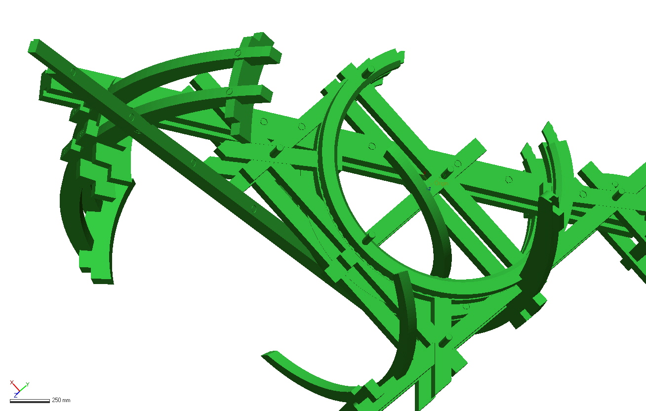
Recreating One of A kind Art Structures
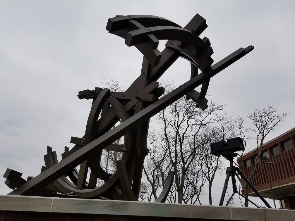
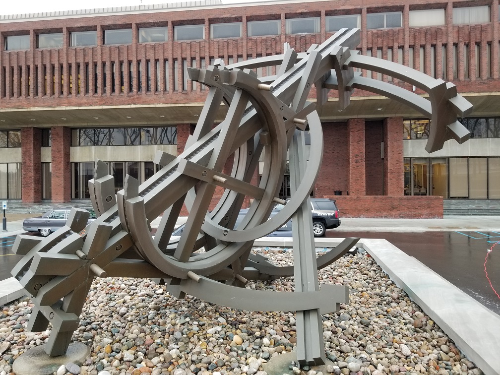
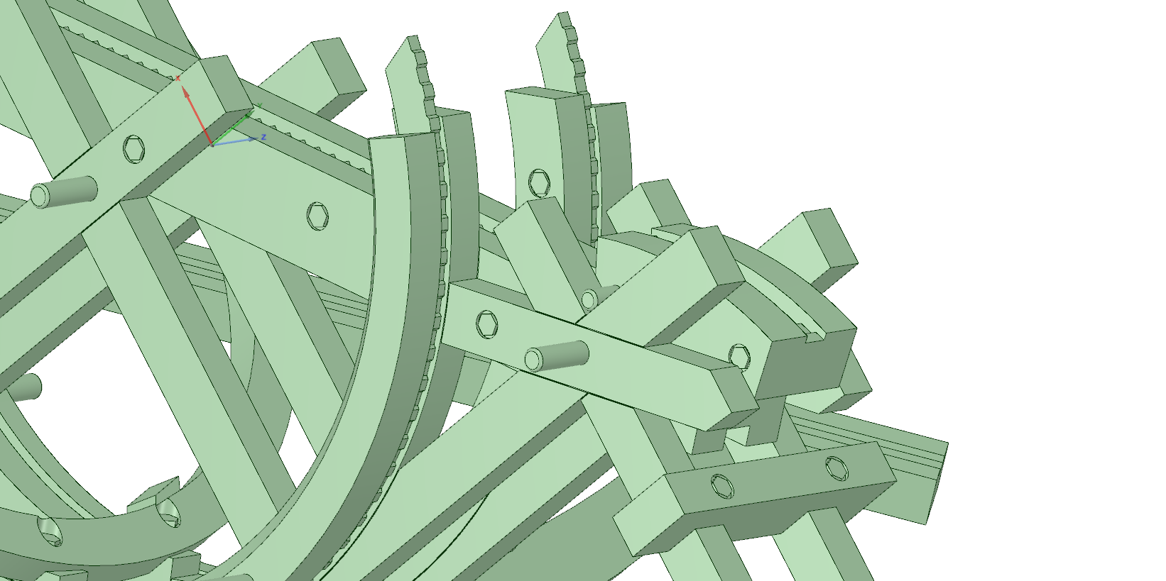
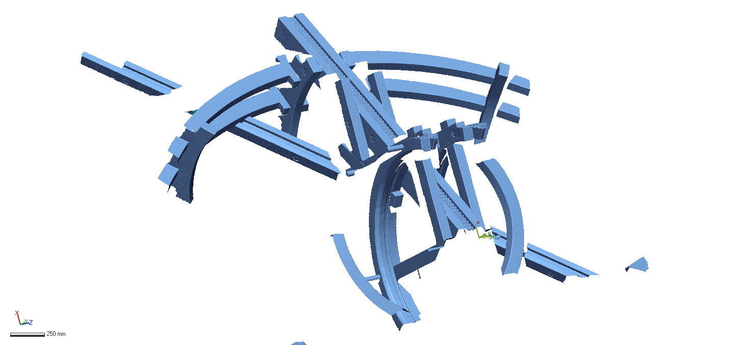
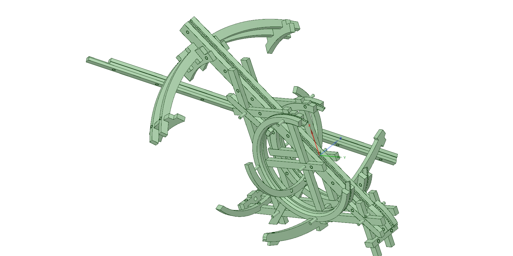
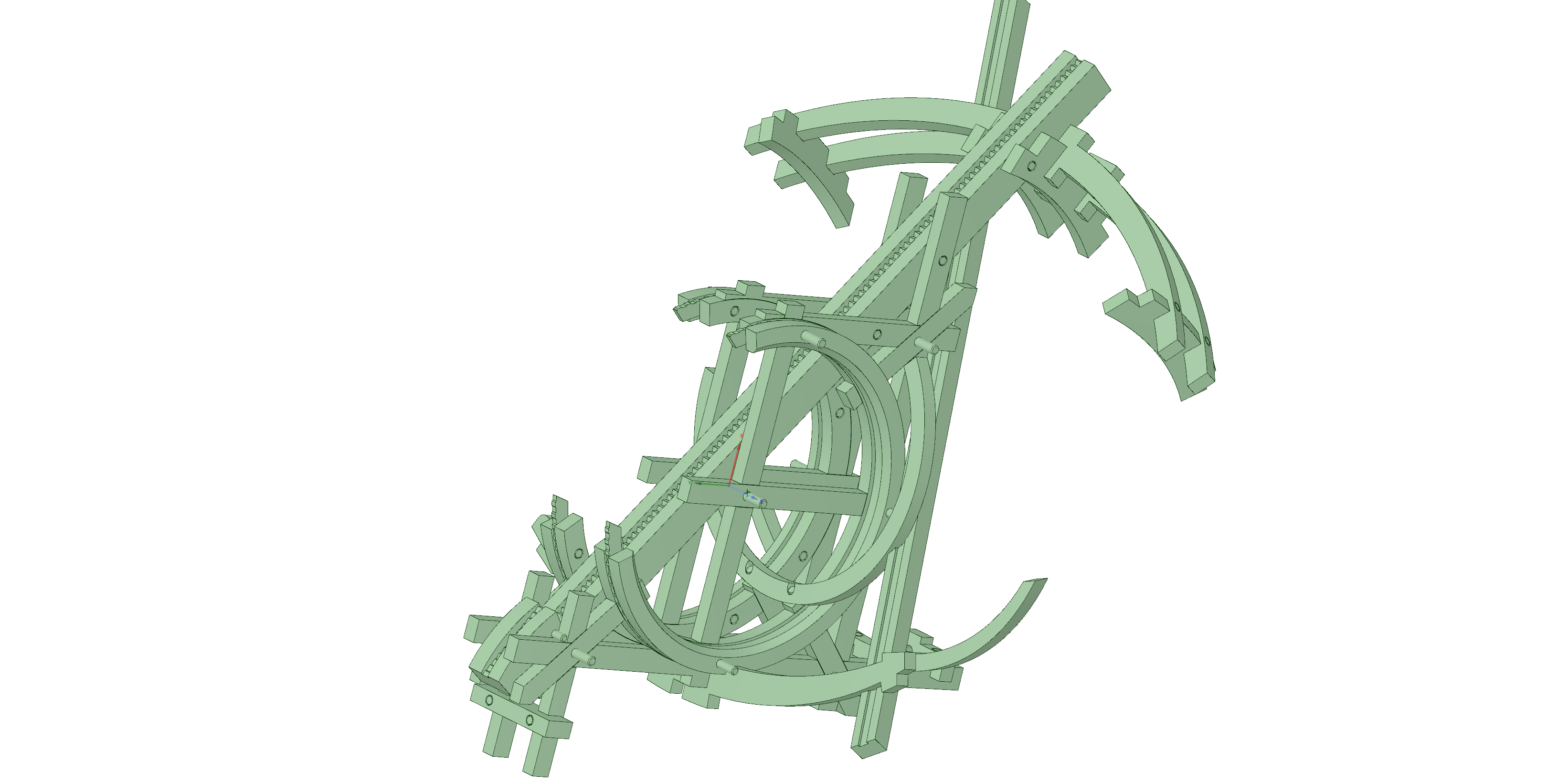
Laser Scanning The Orbits of Issac
Using Surphaser long range scanner to reverse engineer Kettering’s engineering artwork.
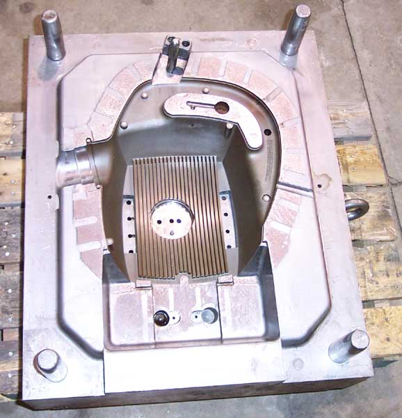
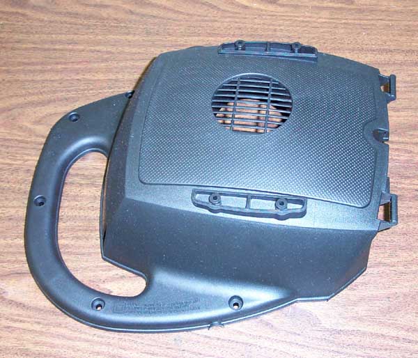
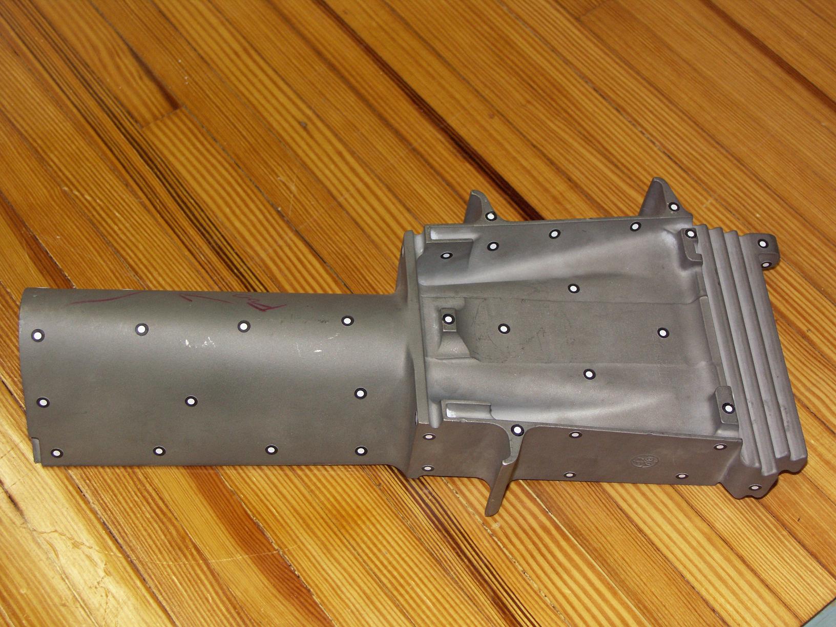
Modifying an Injection Mold with 3D Scanning
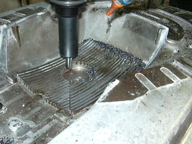
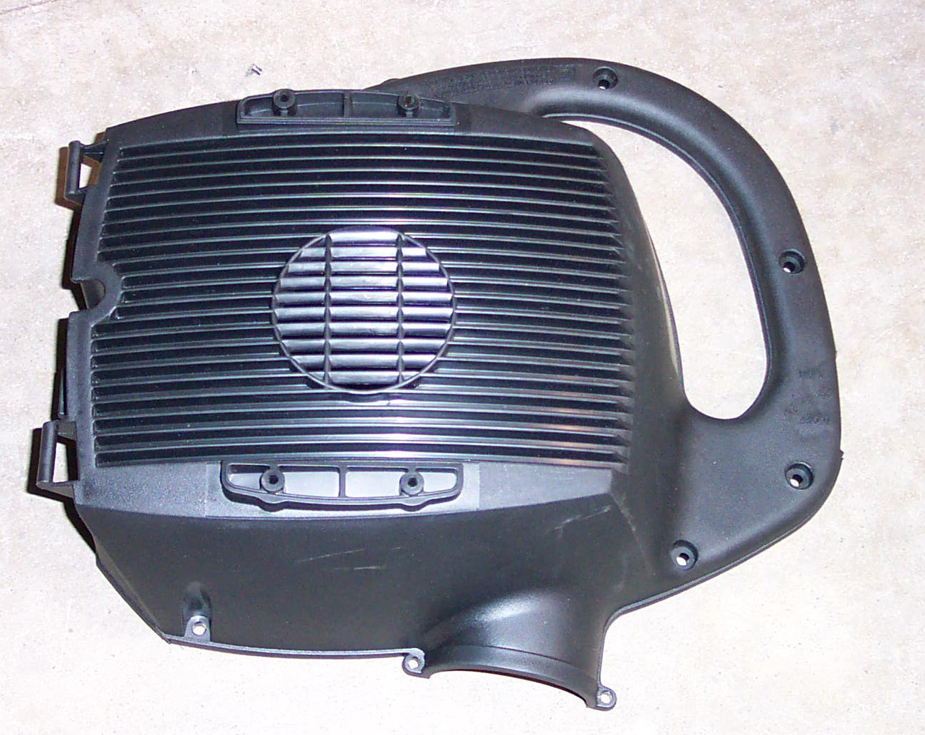
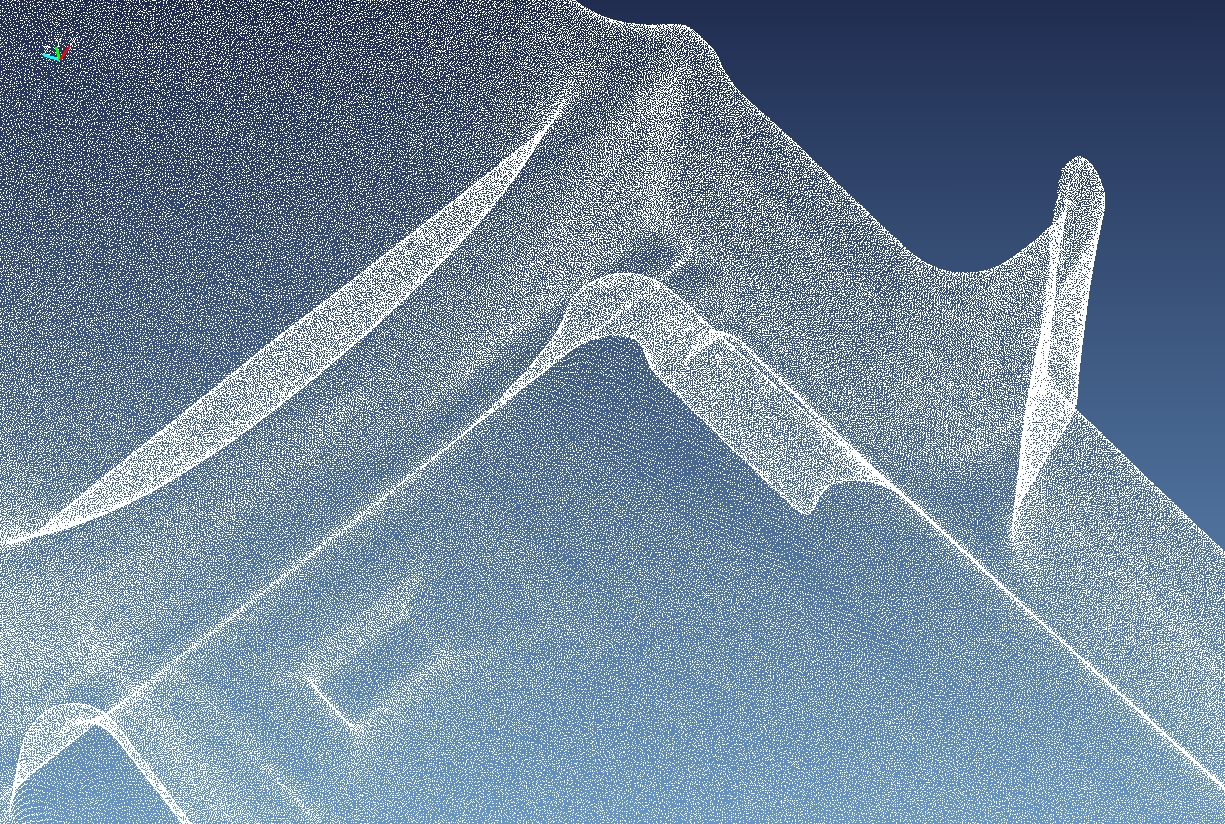
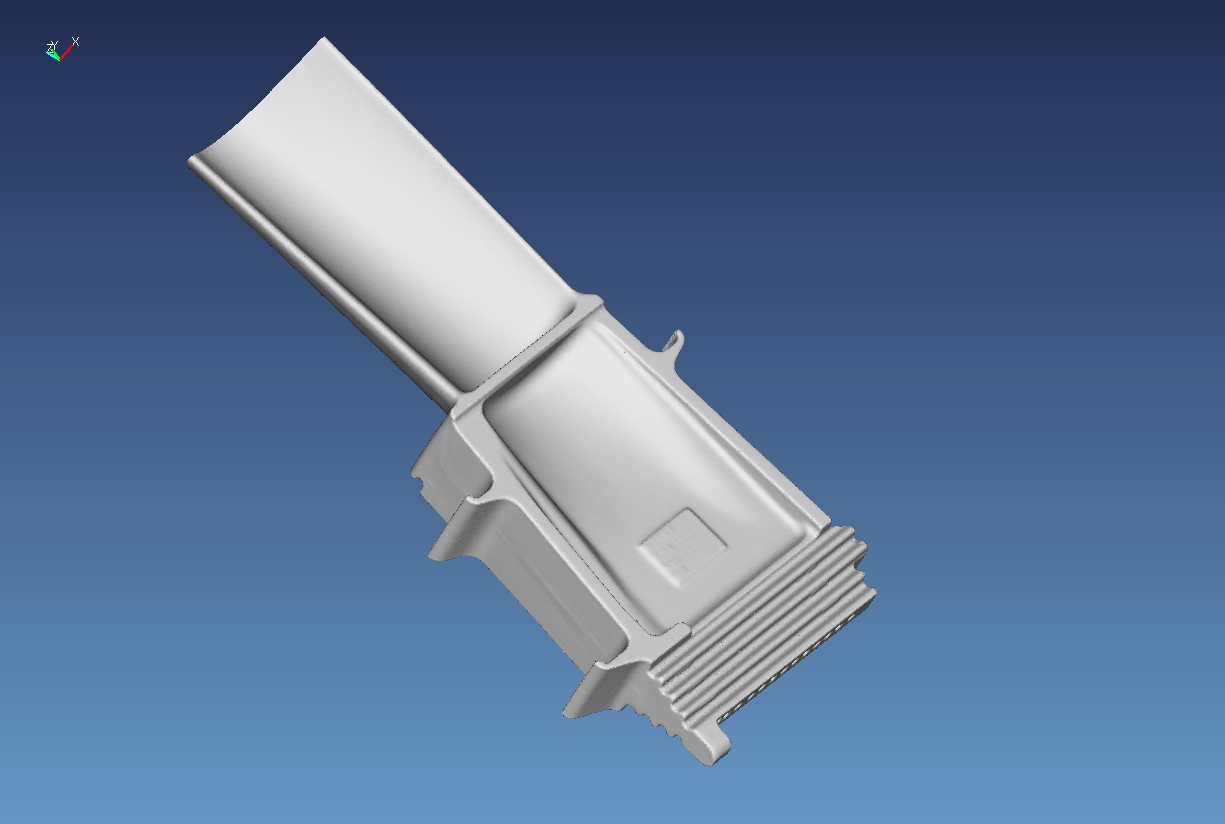
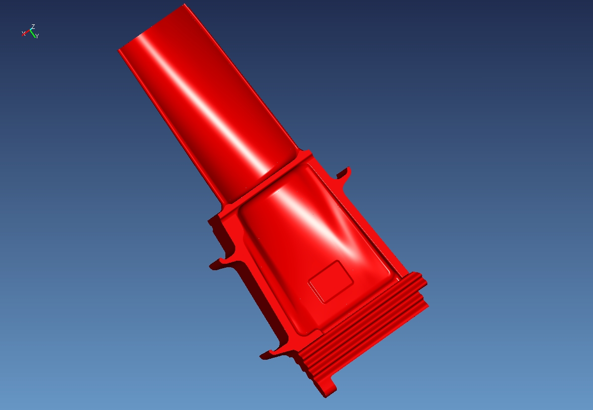
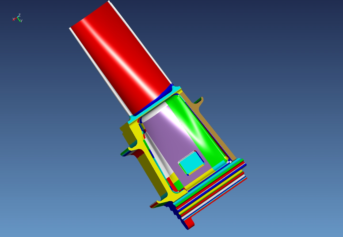
A local mold making company in Windsor was faced with the challenge of modifying a mold for a vacuum cover. The real problem was that the mold had been manufactured by another mold making company and the original data was not provided with the mold.
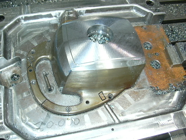
Applications 3D was called in to do 3D scan of the mold and come up with the required math data so that the needed modifications could be performed on the mold. The 3d scanning was performed at the customer’s location on the shop floor. This was possible with Applications 3D‘s mobile and portable digitizing equipment. Since the scanning does not require any reference points to begin with, there was no fixturing of the mold on a reference or granite plate. The whole measurement was completed within a few hours.
The scan data was then moved into a coordinate system using captured guiding information like guide pins and holes from the mold . The relevant areas were then converted from measured xyz points to surfaces. The finishes IGES surface data (also called math data) was finally used to cut and modify the mold using CNC machining. After it was polished and textured the mold was ready to produce the new and improved component!
3D Inspection of a Complex Headlight
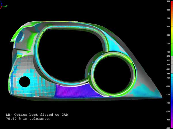
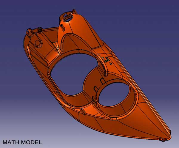
Car headlights aren’t as simple as they appear to be. There is a lot of engineering involved behind their manufacturing, so that they result in pleasant looks as well as attain the required light handling and reflection properties. Since the light flashed from a car’s headlights has to illuminate far away objects in the path of the car, there is extensive testing done on the light reflection properties of the headlight. The headlight consists of an injection molded part which adds to the problem of producing an accurate final part due to the inherent shrinkages and other variables in the molding process. This means the mold has to be near perfect and conform with the design intent within the required tolerances. The mold is dimensionally inspected, and tolerances of two thousandths of an inch are used to decide if the mold is usable or not. Conventional CMM machines do not generate enough measurement points to provide a complete picture of the whole mold. So, they are generally measured by optical scanning systems.
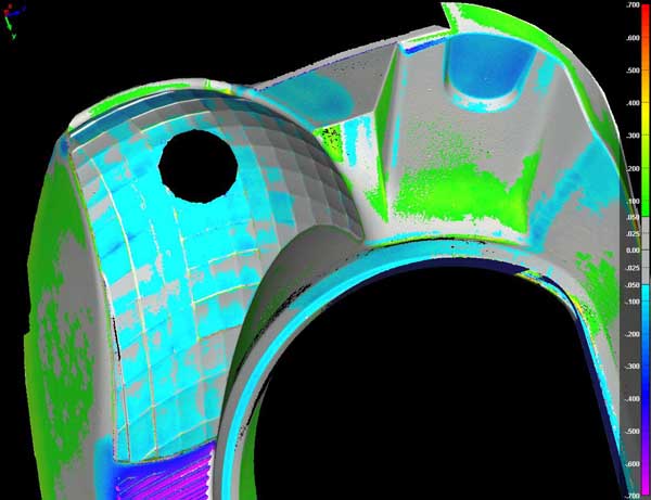
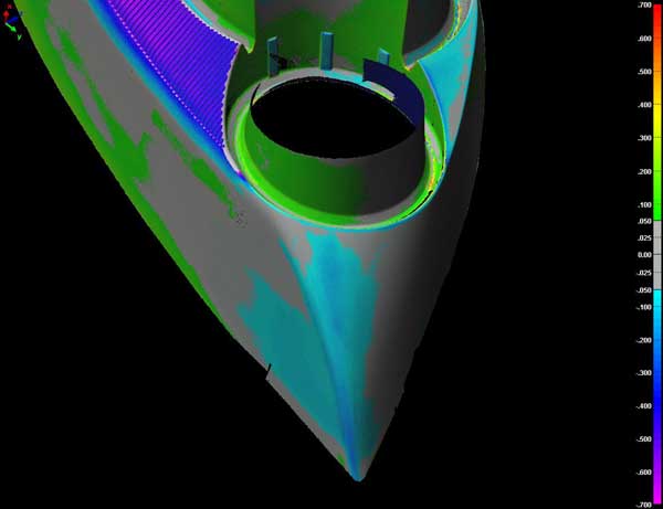
Applications 3D was called in to do such an inspection on an automotive headlight optics mold insert. Since the project was “hot”, it meant that the measurement had to be completed on the weekend at the customer site. The measurement was to be done with a white light scanner with the highest accuracy and resolution so that the complete mold was scanned with no reflective area of the mold remaining unmeasured. This was achieved using the state of the art Steinbichler Comet 75 scanning system. This system consistently achieves accuracies of less than one thousandths of an inch for each measurement. Since this system uses white light as a modus operandi, the mold insert was coated with a micro thin layer of a reflective material. This material is not damaging to the part and can be wiped off with a cloth. The scan was completed on time, resulting in millions of points on the surface of the mold.
This scan data was then compared with the original CAD file of mold, the same file which was used to manufacture the mold. The results of the inspection were provided to the customer in the forms of easy to read color plots which represented each area on the mold with a different color based on how much it was out of tolerance. The in- tolerance areas were shaded grey for easy identification. As well, old fashioned, text reports were also generated for those familiar with CMM type reports. The mold insert was found to be significantly different than the CAD data (or the math data), thus requiring extensive modifications to the mold to conform to the required tolerances.
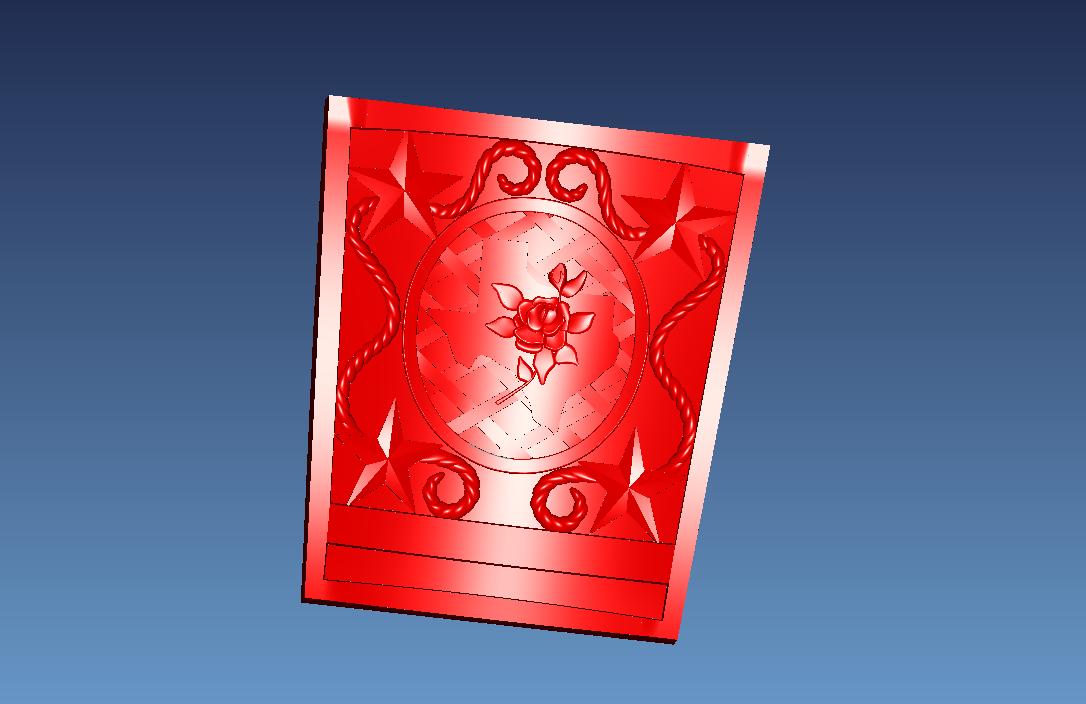
Texas Chair Mold Insert
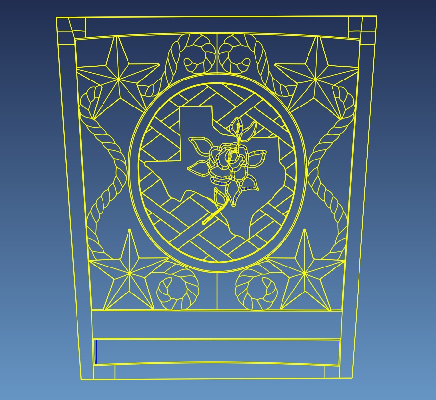
One of our prestigious customers, a mold making company, had a small dilemma. Their customer, who is a plastic chair molder/manufacturer, wanted a special mold for a plastic chair that included the Texas map on it as well as a series of patterns and a rose shape on it. Since the cost of such a mold is substantial, they wanted to build just one insert which could be changed in the mold, so that the mold could become multitasking and produce more than one kind of chair. On top of it, they had just provided a handmade sketch for the mold insert. An ideal art to part strategy was employed to handle the situation. That sketch was used as a basis by an experienced patternmaker to make a full scale clay model that represented the actual mold insert with the proper dimensions to fit in the mold.
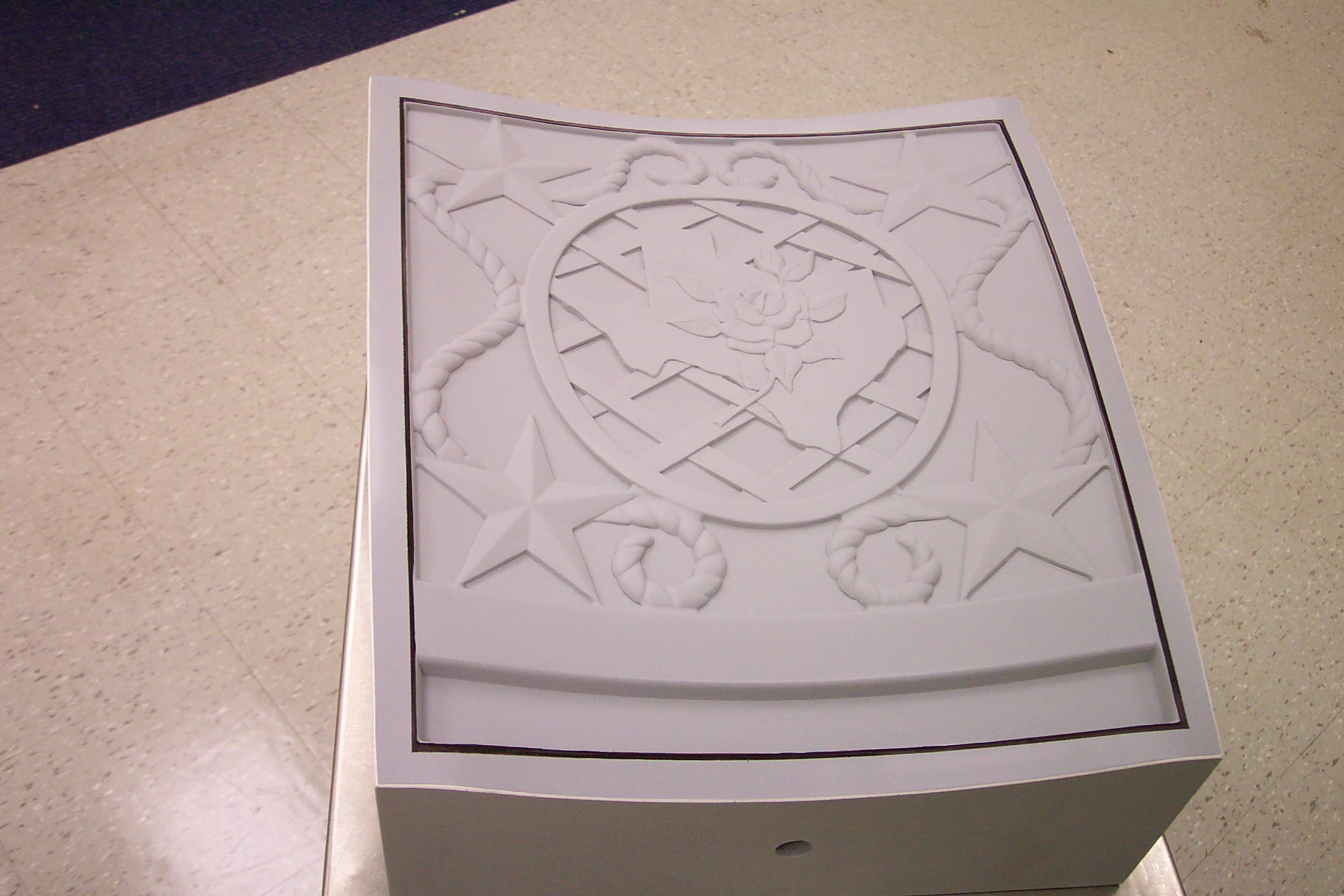
3D Scanning Begins
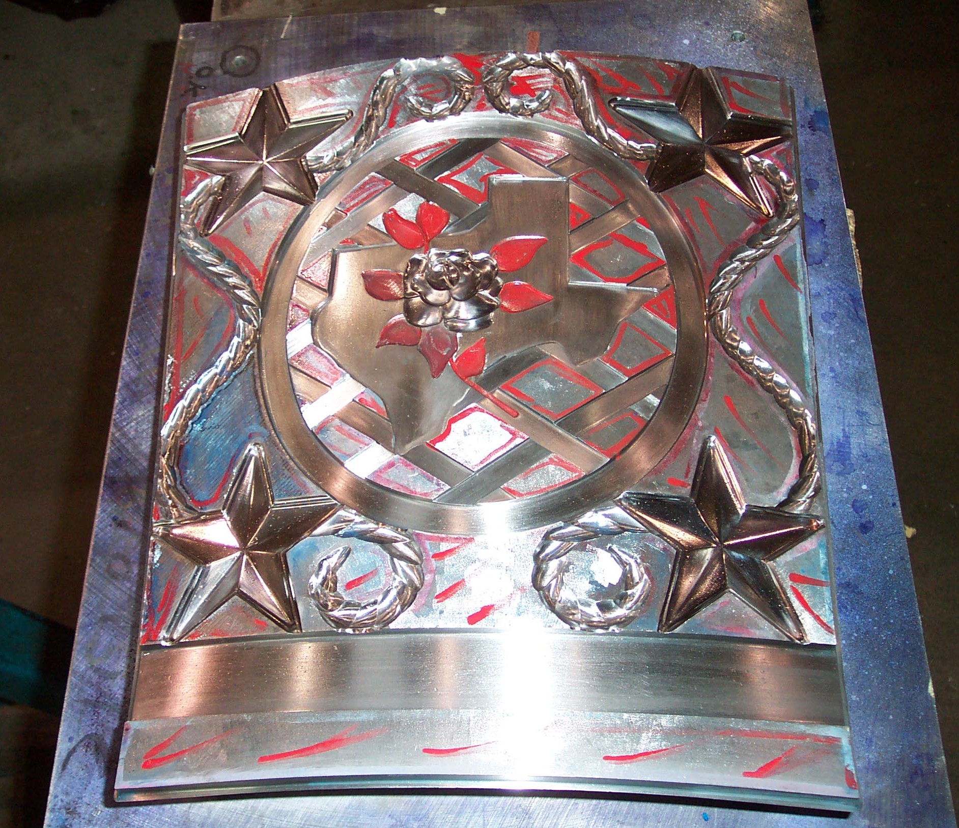
Applications 3D was hired to reverse engineer the clay model into a high quality, workable CAD file. The first step of the reverse engineering was to do an accurate 3d Scanning or digitizing of the model. This was achieved using state of the art Steinbichler Comet 75 white light scanning system. Since this model contained some very fine features, the Comet 75 was an ideal machine to digitize it. The Comet 75 measures 420,000 xyz points in a 2 inch by 3 inch area. That meant a lot of points were to be collected over the whole model. After the scanning was completed, the scan data was processed to form into an STL file, which essentially is a large mesh of 3 sided polygons or triangles. During this process, the data was optimally reduced or “decimated “ to intelligently reduce the number of points on the planar areas and keep a high number of points at the areas of high curvature or small features. This whole process was done on Polyworks, a state of the art point processing software.
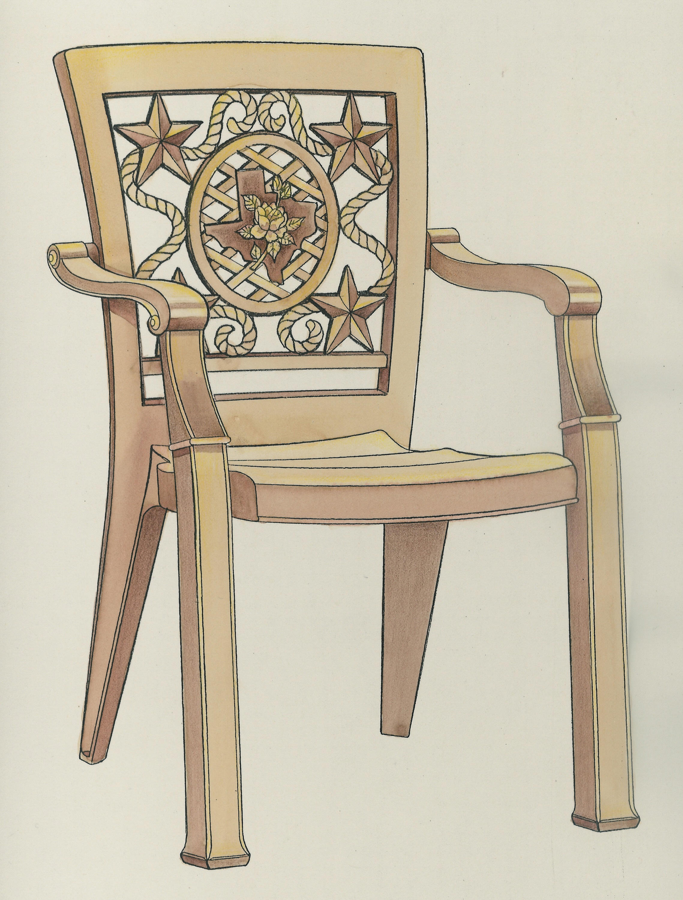
Reverse engineering from scans
The STL file was then used to manually convert each feature and shape into a high quality, high accuracy surface. This engineering grade surfacing was performed on Imageware, one of the world’s best freeform surface modeling tools. Not only did the surface model look good, it also conformed to the stringent accuracy and continuity requirements of the downstream mold designing and machining softwares. The IGES surface model was used to program the cutter paths for the CNC machines and was eventually used to machine the insert successfully by our customer. It fitted well in the mold and is now mass producing the custom chairs!
Reverse Engineering
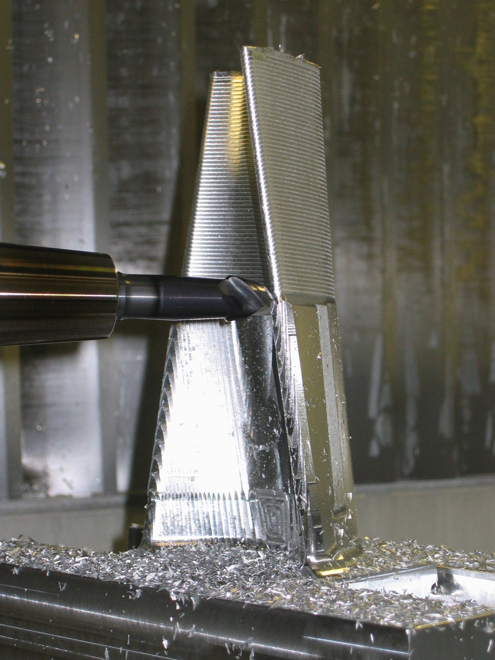
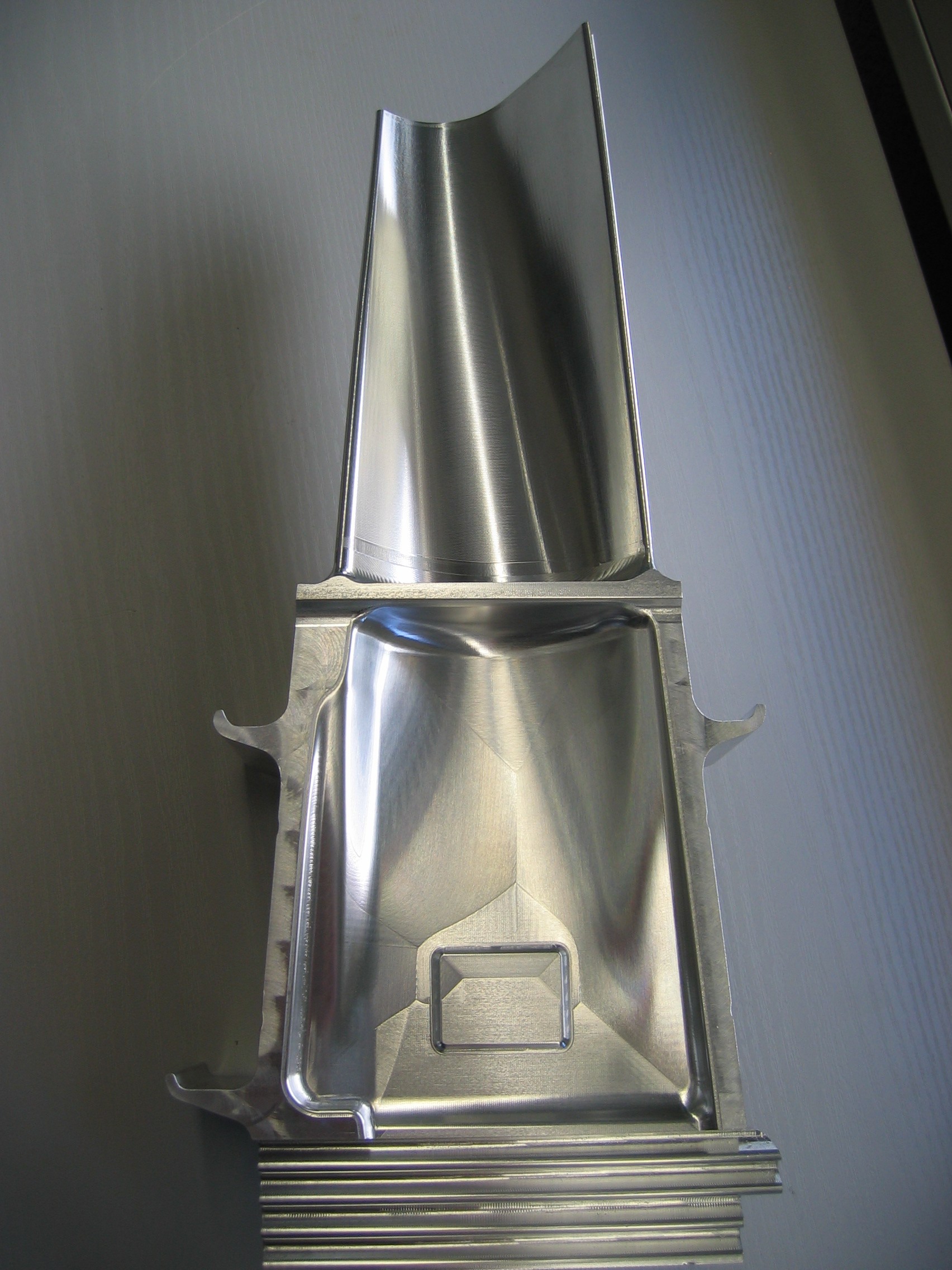
One of the biggest power generation systems manufacturers in North America wanted to design a new manufacturing process to produce steam turbine buckets. Since it was a tryout process and the old turbine buckets were made by a different process, the old turbines were 3d scanned to generate the math data for them. After the scanning was done, the data was then manually converted to a high quality industrial grade surface model. It was then further converted into an IGES solid model to use as a basis for CNC machining. The machining was performed in Germany by a well known CNC machine manufacturer. The machining was done from a whole block of steel since the turbines do not have any joints or welds in them. Since the solid model was already generated, it was easy to analyze and modify on the computer. This process proved to be a viable solution for manufacturing turbines in mass scale, saving time and resources in the long run.
Apart from this , different inspection reports for the manufactured turbines can be generated:
- Leading and trailing edge measurements
- Cross sections
- Airfoil shape
- Complete 100% coverage of the entire part
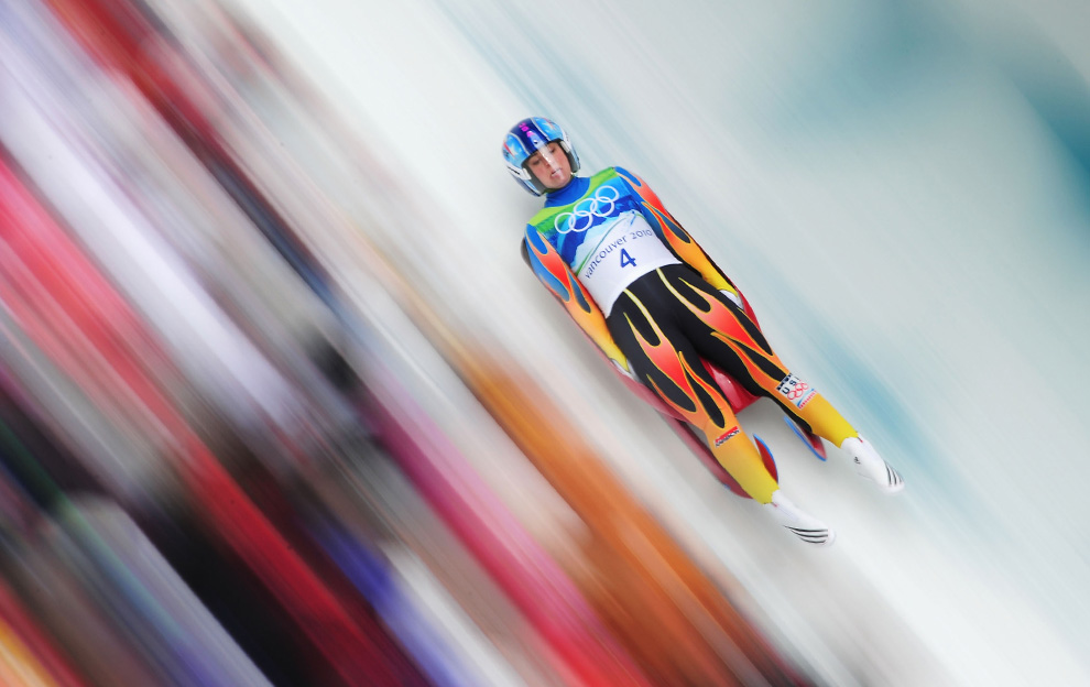
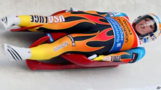
US Olympic Luge Team Goes Faster!
The fastest sport on ice just became faster ! When The US national Olympic team was looking for an edge to improve their luge sleds, they contacted DOW, an international manufacturer of materials. The DOW company researches new materials and develops customized revolutionary materials, designed for a specific purpose.
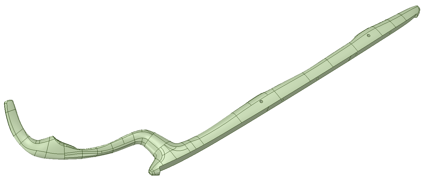
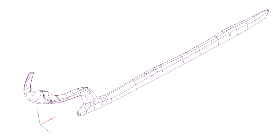
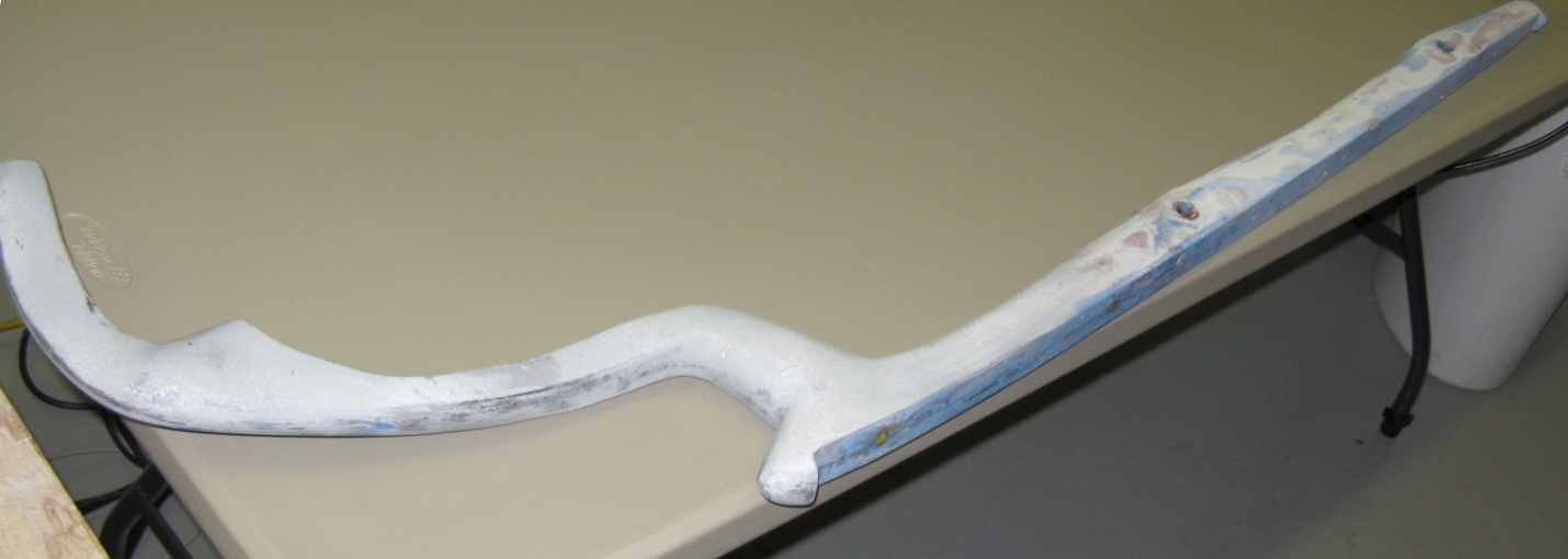
Since the luge was going to be made of a newly developed custom material, the shape of the luge also played a big part in the functionality. A special clay modeler was hired to articulate an existing idea into the physical shape of the new luge blade. Once the clay model of the new blade was approved, Applications 3D was contracted by DOW to provide 3d scanning and reverse engineering services.
Applications 3D used the latest Steinbichler Comet 5 white light 3d scanning technology to accurately measure millions of points on the full shape of the luge. We were able to capture the complete shape into a digital format. Once, the scanning was completed, the millions of points were optimized into a single skin mesh of triangles, called an STL ( Stereo Lithography) model. This model was then reverse engineered into an engineering grade surface model, by surfacing over all the intricate freeform shapes. The final surfaces were then stitched into a single solid model and exported as a step solid format.
This final 3D shape was then incorporated into the new luge design for manufacturing.
Go Team USA !
Applications 3D is an expert provider of 3d scanning, reverse engineering, inspection and product design services. Based in Metro Detroit, Michigan
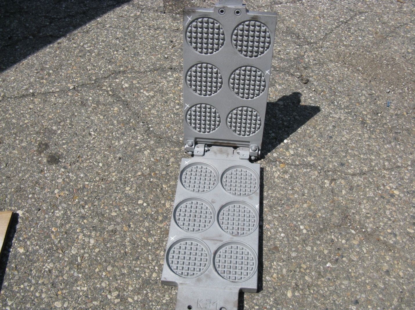
Creating the Perfect Waffle!
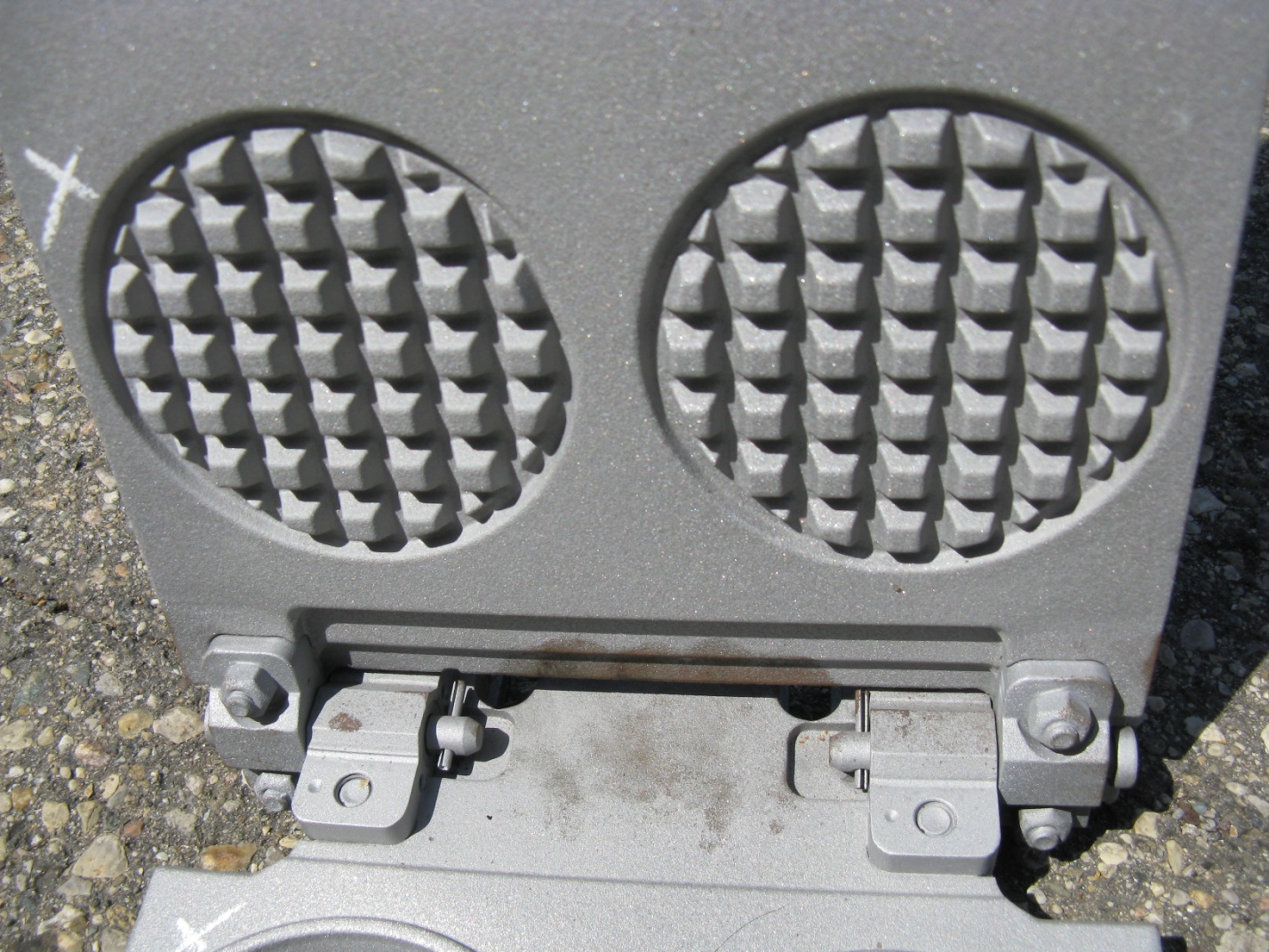
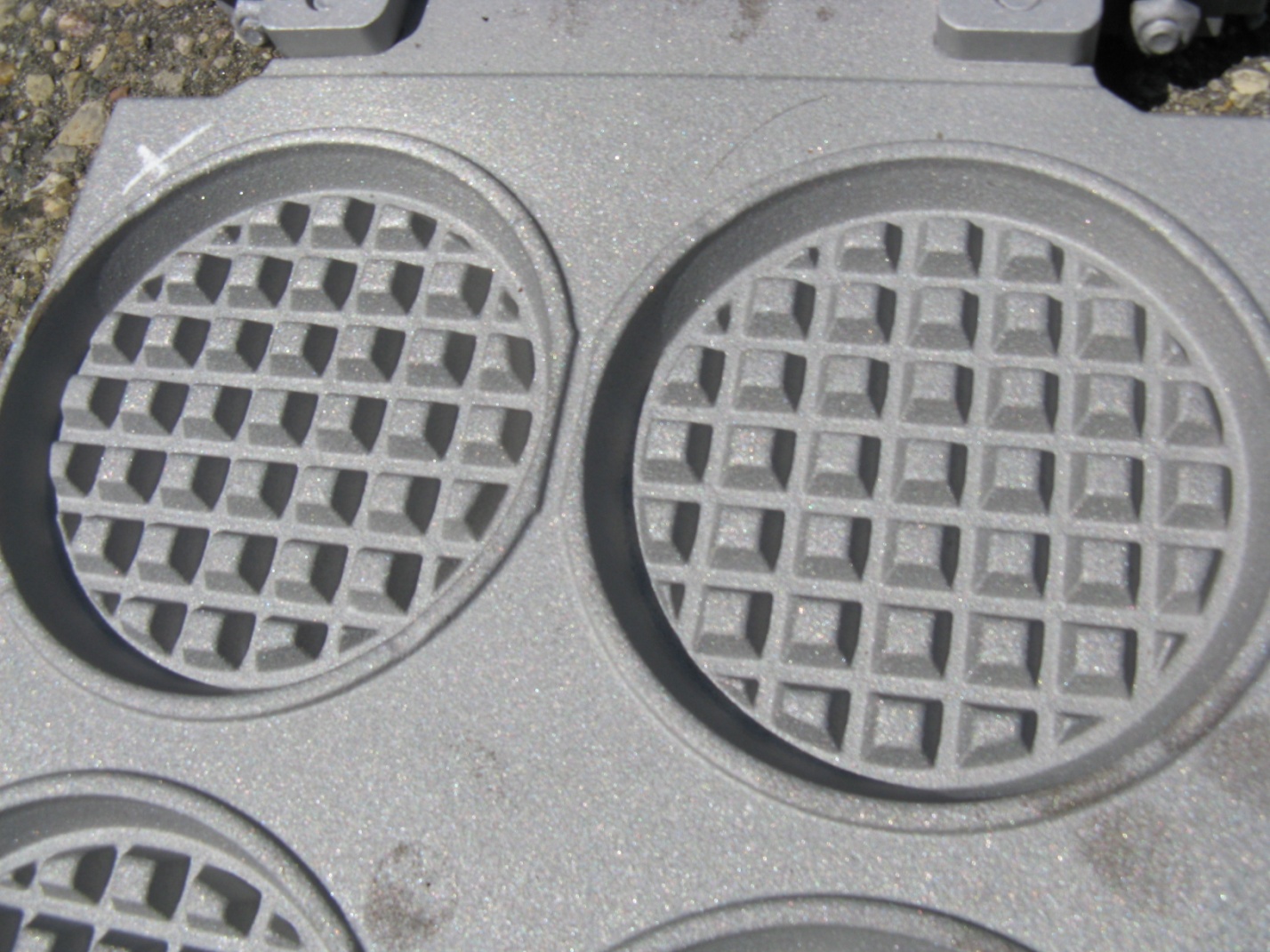
A nationally leading manufacturer of frozen waffles had a unique but age old problem. When manufacturing the waffles in a hot mold, how much waffle batter mix to add to the mold for each waffle? Since the waffle molds were usually cast steel tools, there was a lot of variation between the different cavities.
If they put too little batter mix, it would result in an incomplete waffle, which could not be sold, and was thrown in waste, costing $$$$’s…..
If they put too much then they were wasting the extra material that poured out of the molds during the cooking process! Again, that cost $$$$’s….
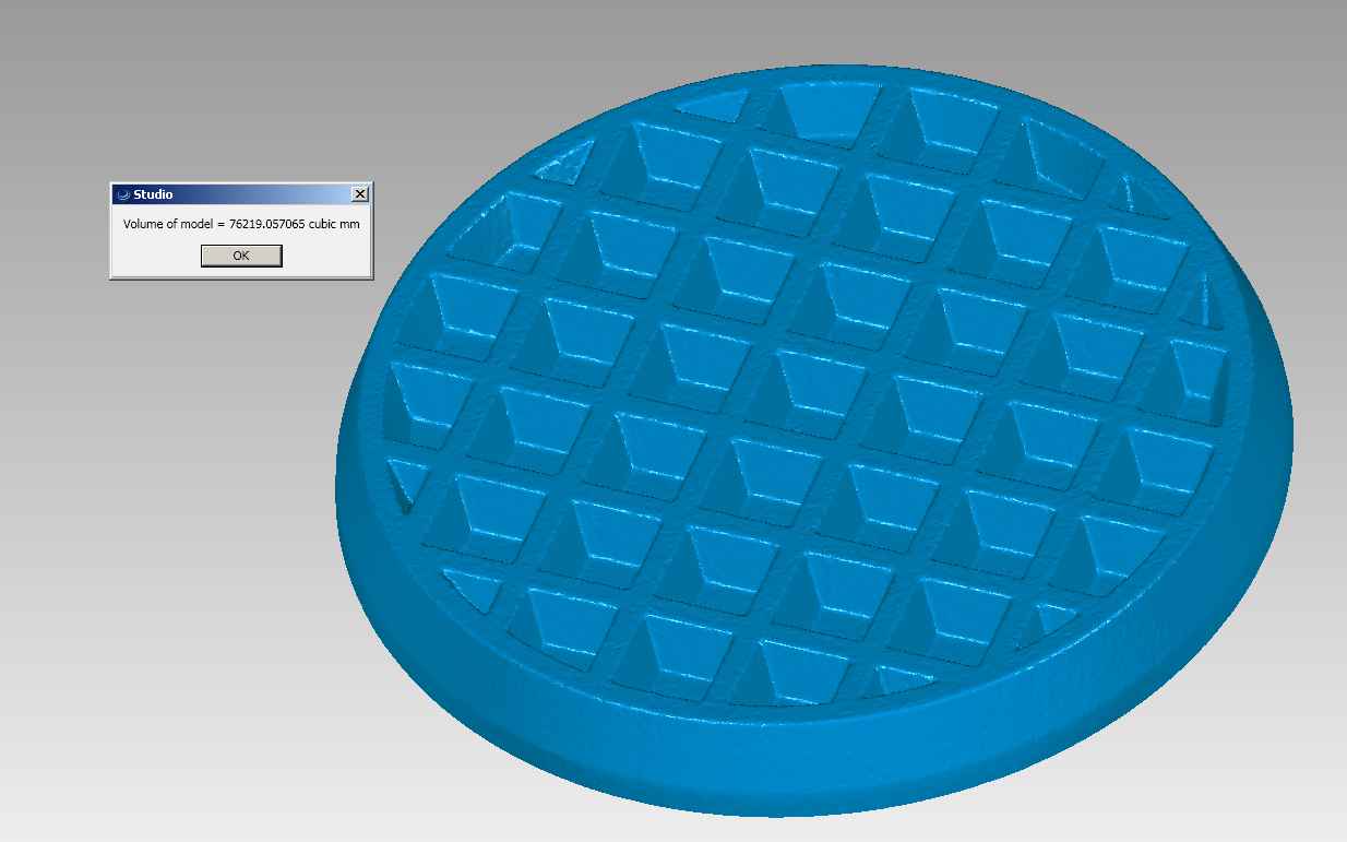
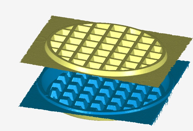
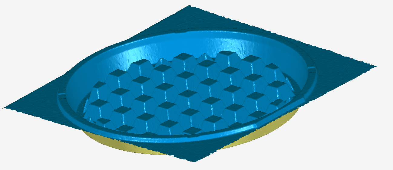
This unique challenge was solved by Applications 3D in a simple way. Both the cavities of the mold were 3d scanned with high resolution white light 3d (WLS) scanning, done with the Steinbichler Comet 5 3d scanner. The resulting scandata was processed into stl models using Geomagic Studio software. This advanced digital modeling program allowed us to create a digital assembly of the two halves of the mold. Both the top and bottom cavities were combined together to a perfect closed volume 3d stl model. Geomagic Studio’s advanced polygon editing tools allowed for the perfect editing and matching of the two models into one single model.
This 3d stl model was then analyzed in Geomagic Studio to determine the actual volume of the closed mold cavity.
Using these figures for each cavity in the mold, the manufacturing of perfect waffles was achieved!
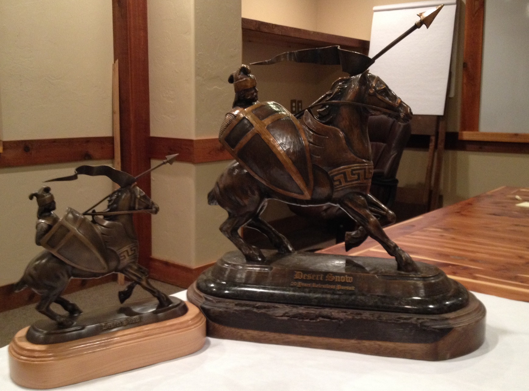
3D scanning helped create a masterpiece for Honoring Exemplary officers !
The Desert Snow Training Program has provided the law enforcement community with the finest interdiction training available on the market since 1989. The Black Asphalt website has provided the law enforcement community with the most comprehensive networking tools available since 2004. Together, these companies have helped officers apprehend and remove thousands of major criminals from our streets and communities.
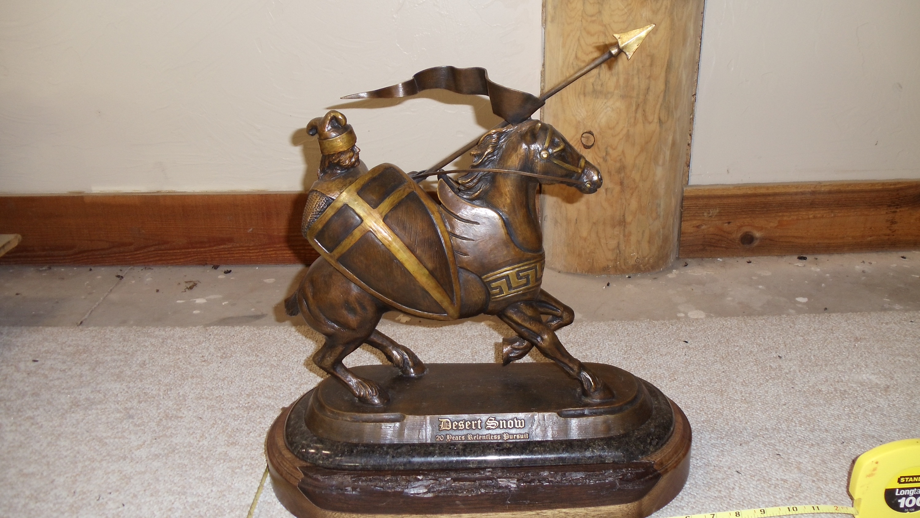
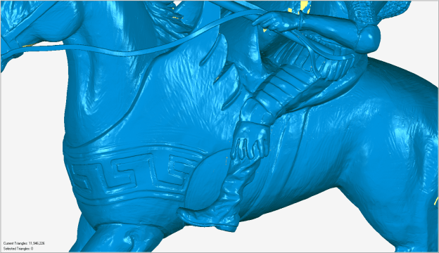
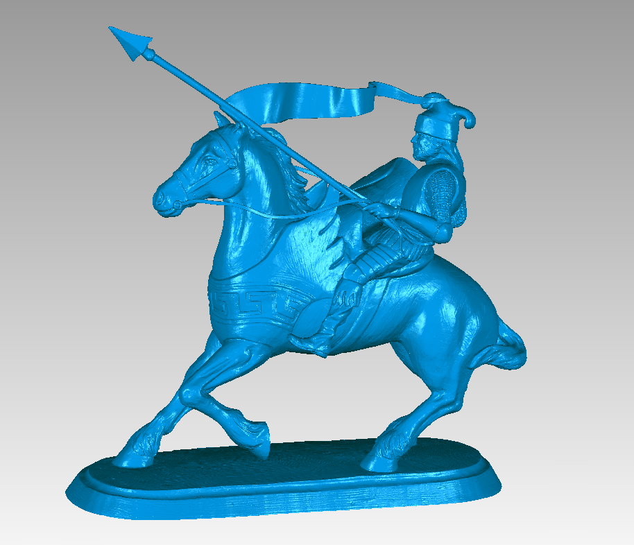
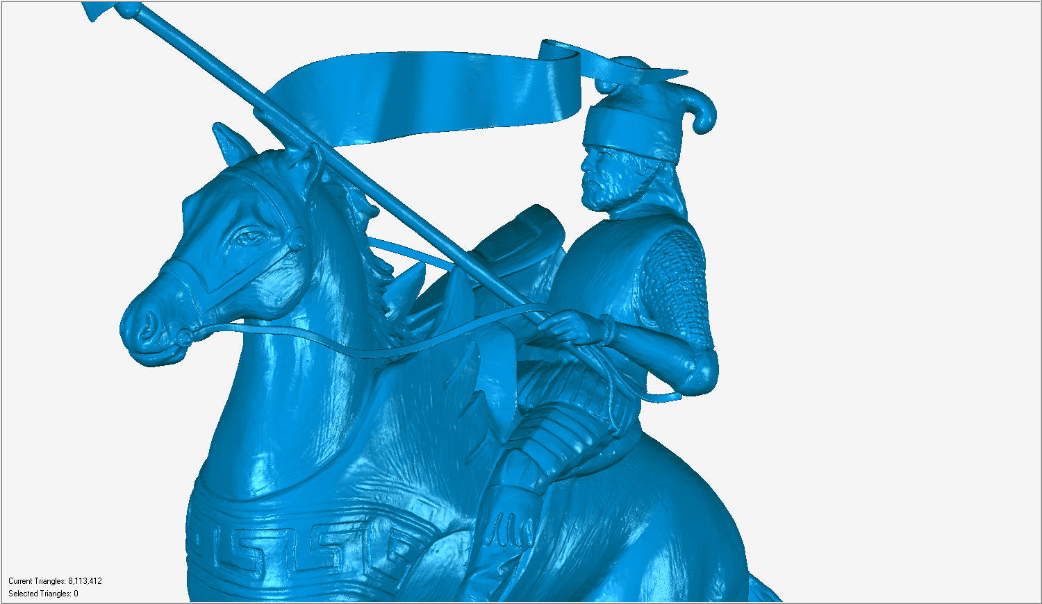
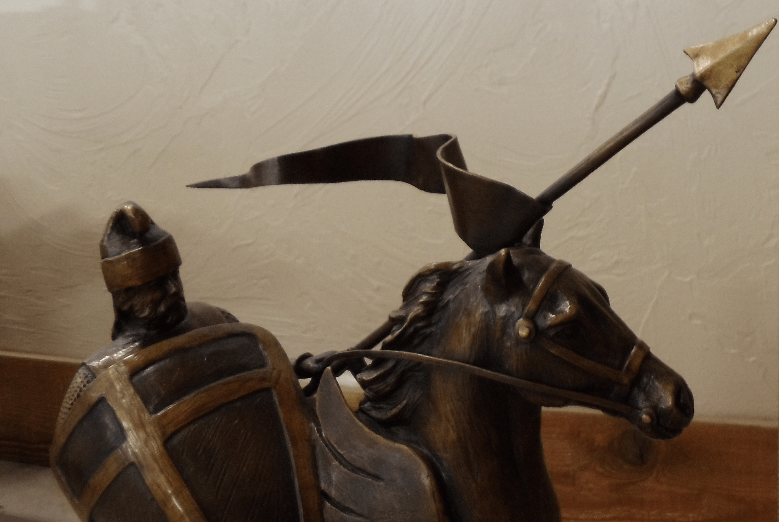
Desert Snow honors many illustrious law enforcement officers during it annual conventions. This one-of-a-kind mascot represented the attributes of the work involved, it was decided to be presented during the annual ceremonies.
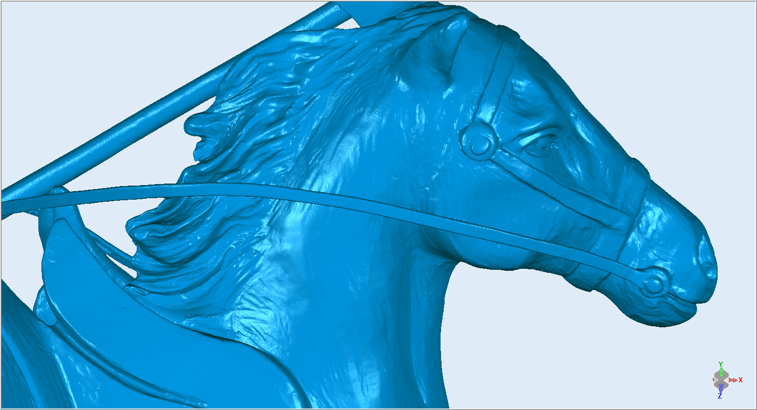
The problem was: This sculpture was one of a kind, and the award sculpture was going to be much smaller than the original. So, it was decided to reverse engineer this casting to make a new bronze cast for creating smaller multiple bronze copies of the original sculpture.
3D Scanning
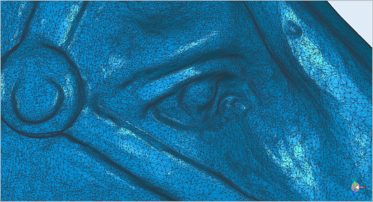
Applications 3D was contracted to provide the 3d scanning, reverse engineering and 3D printing services. The 3D scanning was done using Steinbichler Comet 5 white light scanning system. This high resolution digitizing machine facilitated the collection of tens of millions of highly accurate x,y,z points on the surface of the sculpture. These points were then meshed together into a triangular polygon model.
This digital shape modeling was done in the state of the art Geomagic Studio© software. Geomagic is a leading provider of 3D software for creating digital models of physical objects for reverse engineering, product design, inspection and analysis. It’s advanced tools, powerful interface, ease of use and potent automation technology makes Geomagic the industry leader in its class.
In Studio, the scanned polygon model was first optimized. We decimated the points on the flatter areas, while keeping a larger number of points on the more featured areas. During this automatic process, other abnormalities in the data were also repaired, and the model was scaled down in size to the smaller required size. Any missing data was filled in using curvature continuity methods, so that the missing areas were represented as close to the original as possible. The resulting model was finally a watertight STL model!
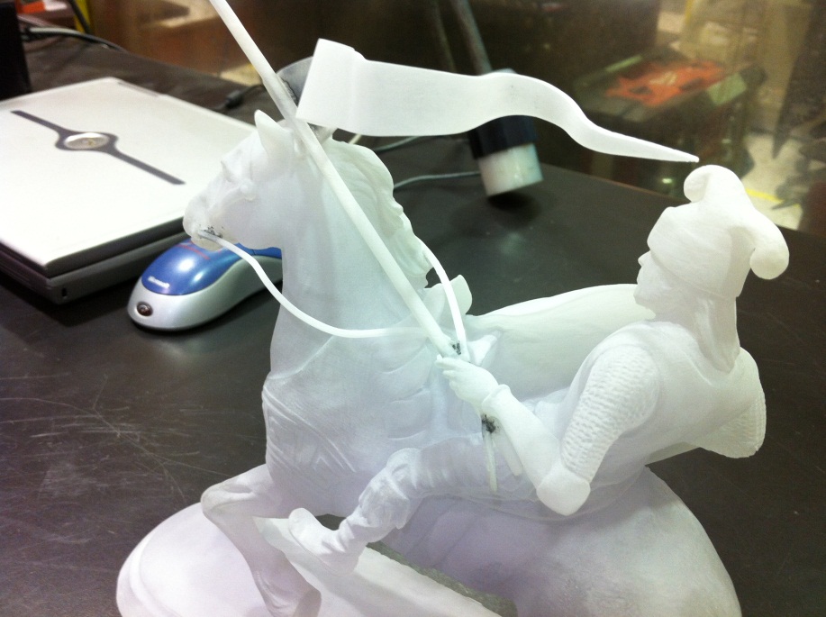
Building the final model
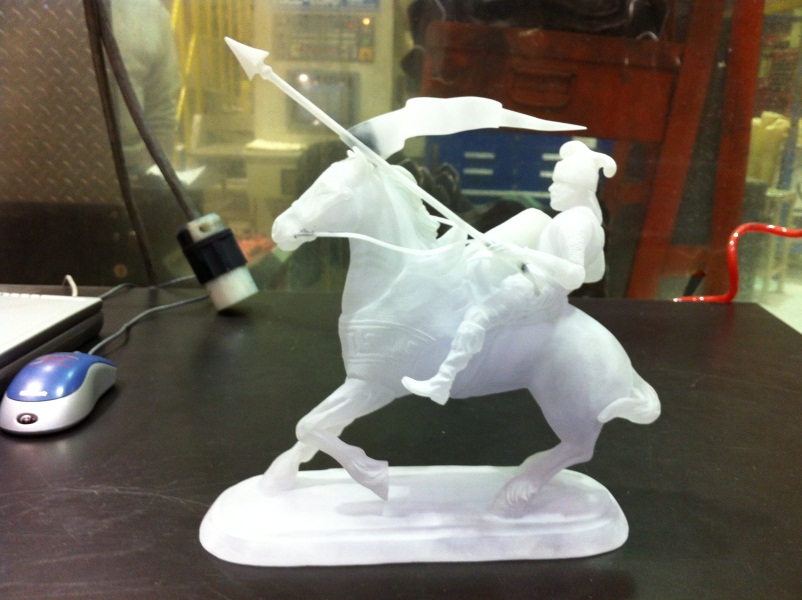
The next step was the creation of an actual physical model, for use as a pattern for making the bronze production. The challenge at this stage was to accurately build all the finer details in the model. This was done by using the finished STL model to 3D print a physical SLA model. The intricate shape of the STL model proved to be a challenge. But this was achieved with flying colors by 3 Dimensional Services
of Rochester Hills,MI, with their advanced 3d printing and prototyping capabilities. During the build, due to the complex shape of the STL model, the 3D print kept failing. But , after repeated attempts, a perfect model of the knight with the horse and intricate details like the reins and spear, were built successfully!
This SLA model was then used by the bronze cast maker as a pattern to make the tool for producing the smaller sized sculptures for the award ceremony!